Husky 1250

Operator's and Maintenance Manual

Page 9

Figure 16

P.T.O. BELT ADJUSTMENT (See Figure 18.)

Should it become necessary to replace P.T.O. belt, install new belt as follows:

1. Place P.T.O. lever in the ON position.

2. Loosen hex capscrew which secures upper belt guide, and adjust for a 1/8 inch clearance between belt guide and newly installed belts. Tighten hex capscrew securely.

POWER TAKE-OFF (P.T.O.) LEVER (See Figure 17.)

1. Place P.T.O. lever in the OFF position.

2. Remove spring cotter pin and turn the P.T.O. control rod until the desired tension is obtained, or the "over-the-center" snap is felt when moving the P.T.O. lever from OFF position to ON position. Reinstall spring cotter pin.
3. Loosen the two hex capscrews which secure the lower belt guide, and adjust for a 3/32 to 1/8 inch clearance between belt guide and belts. Tighten the two hex capscrews securely. Place P.T.O. lever in OFF position.


GENERATOR STARTER BELT

Figure 17

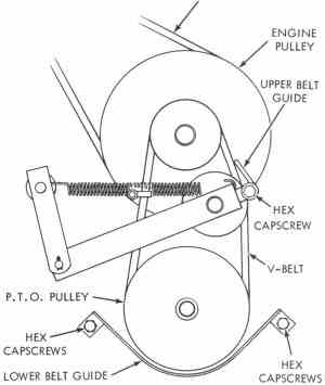
3. With the P.T.O. lever still in the ON position, loosen the hex capscrew which secures the upper belt guide shown in Figure 18. Adjust upper belt guide for a 1/8 inch clearance between belt and belt guide. Tighten hex capscrew securely.

Figure 18

DISC BRAKE (See Figures 21 and 22.)

1. Remove cotter pin and clevis pin from brake rod assembly.

2. Hold brake pedal in its normal relaxed position. Turn end yoke until one inch of free brake pedal


Previous

Page 10

Contents

Home