|

CAUTION
DO NOT ENGAGE ATTACHMENT DRIVE WITHOUT AN IMPLEMENT
ATTACHED. ALWAYS REMOVE UNIVERSAL JOINTS FROM ATTACHMENT DRIVE SHAFT AFTER ATTACHMENT IS
REMOVED. SERIOUS DAMAGE WILL RESULT IF UNIVERSAL JOINTS ARE LEFT ON AND ATTACHMENT DRIVE IS
ENGAGED.
|
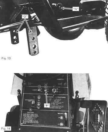
The Attachment Drive Shaft is located under the front of the tractor frame and is connected to the engine by two drive
belts. The attachment drive shaft is splined at both ends so that front, center and rear power attachments can be coupled directly to it.
To connect drive to attachment proceed as
follows: Liberally grease end of splined attachment drive to be used.
|
Liberally grease rectangular drive shaft on
attachment. Slide rectangular drive shaft into universal joint.
Depress locking collar on universal joint and slide over end of attachment drive shaft and lock in groove in
shaft.
If the attachment drive is to be used when operator is off of the tractor
seat, tip seat up and pull interlock button up.
|