|
3. The third is on the brake linkage.
4. The brake interlock switch is spring actuated and should not need adjustment. If for any reason the switch should be readjusted, the clip for the actuating spring (U) figure 33, should be positioned midway between the threaded portion and the ratchet section on the brake rod.
ATTACHMENT DRIVE BELTS
Should it become necessary to replace Attachment Drive belts, install new belts as
follows:
1. Place switch in OFF position.
2. Remove hood as outlined under hood
removal.
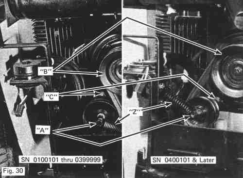
3. Unhook spring (Z) from idler shaft (A) figure 30.
4. Remove old belts.
5. Reverse the above procedure to install the new
belts.
ATTACHMENT DRIVE CLUTCH
(B) Figure 30

CAUTION
UNITS ABOVE SERIAL NO. 0200101 ARE EQUIPPED WITH AN AUTOMATIC CLUTCH FRICTION BRAKE. THE FOUR BOLTS (C) IN FIGURE 30 ARE USED TO ADJUST THIS BRAKE. THIS ADJUSTMENT IS VERY CRITICAL AND SHOULD ONLY BE PERFORMED BY AN AUTHORIZED BOLENS DEALER.
|