|

CAUTION
TO AVOID DAMAGE TO THE ALTERNATOR SYSTEM, MAKE SURE THE FOLLOWING PRECAUTIONS ARE
TAKEN.
1. Battery polarity must be correct negative (-) battery terminal is connected to
ground.
2. Rectifier-Regulator must be in common ground with engine and
battery.
|
3. Disconnect plug from RegulatorRectifier if arc welding is done on equipment in common ground with
engine.
4. Disconnect battery to regulator lead when battery is being
recharged.
5. DO NOT operate engine with batter disconnected from Alternator System.
INTERLOCK SWITCHES
This unit is equipped with 3 interlock switches. |
The function of these safety
switches is to insure SAFE START-UP and safe operation of the unit.
1. One switch is incorporated into the Attachment Drive
Switch.
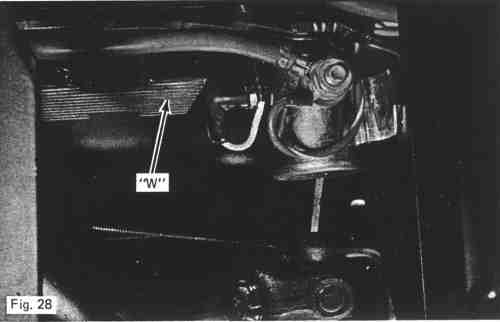
2. The second switch (V) is below the seat see figure 21. This switch should be activated when back edge of seat suppor (W) is depressed 5/8 (1.6 cm). If not, loosen bracket (X) and move to correct location. The switch can also be activate by raising the seat and lifting the interlock button (Y) up.
|